


Lynx T6-8 LED Warning Light
Professional Installation Manual
Important Notice
This manual applies only to the Lynx T6-8 LED Warning Light. Installation and control information below is based on the supplied Lynx T6-8 wiring schematic and product image.
This warning device is intended to improve vehicle visibility. The use of warning lighting does not guarantee that other motorists or pedestrians will see or react to the signal. The operator remains responsible for safe vehicle operation at all times.
Improper installation, incorrect wiring, or unsecured mounting may result in reduced performance, product damage, vehicle damage, or personal injury.
Warnings and Notices for Users and Installers
- Read this manual fully before installation and use.
- Inspect and bench-test the unit before final installation.
- Do not operate the unit with exposed or unprotected wiring.
- Route all wiring away from sharp edges, heat sources, and moving components.
- Do not install wiring or controls in airbag or SRS deployment zones.
- Do not assume warning lighting grants right of way.
Safety Warnings
- Do NOT look directly into illuminated LEDs at close range.
- Disconnect vehicle power before making or changing wiring connections.
- Use a 10 A fuse for one Lynx T6-8. The optional cigarette-lighter plug includes a fuse; hardwired installation requires a separately supplied 10 A fuse and fuse holder.
- Do not open or modify the light housing.
- Secure all wiring with loom, grommets, and cable ties where appropriate.
- Confirm that the selected light color and operating mode comply with applicable laws before use.
Notice of Liability
Manufacturer assumes no liability for improper installation, incorrect wiring, misuse, or operation that does not comply with applicable law.
The user and installer are responsible for proper mounting, correct wiring, safe operation, and legal compliance.
Legal Compliance
Before operating this light, confirm that the selected color and flash pattern comply with your local and state laws. Visit the State Statutes Knowledge Base for complete details.
Maintenance
- Clean the lens with water and a soft cloth only.
- Do not use pressure washers, harsh solvents, or abrasive cleaners.
- Inspect wiring and mounting security regularly.
- Test all operating functions before each use where practical.
Product Overview

| Item | Specification |
|---|---|
| Model | Lynx T6-8 |
| Product Type | Compact LED warning light |
| Dimensions | 35 5/8" x 2" x 1.5" |
| Weight | 4 lbs |
| LED Count | 48 LEDs |
| LED Rating | 3-Watt LEDs |
| Lens Type | TIR |
| Flash Patterns | 36 |
| Memory | Dual Memory with 2 saved patterns |
| Max Amp Draw | 1.25 A flashing; 6 A steady-on at 12V |
| IP Rating | IP67 for light heads and housing; optional circuit-board waterproofing required for exterior use |
| Power Input | 12V nominal; 12–18V DC only. Do not connect to 24V. |
| Power Connection | Hardwire standard; optional fused cigarette-lighter plug sold separately |
| Control Leads | Mode, Memory 1, Memory 2, SYNC |
| Ground | GND lead |
| Synchronization | Current Lynx T6 and L6 lights |
Key Features
- Compact dual-module LED warning-light design
- Dedicated Mode control lead
- Two separate memory control leads
- Synchronization control lead
- 12–18V DC power input with dedicated ground (12V nominal)
Included / Connection Components
- Lynx T6-8 LED Warning Light
- Attached wiring harness
- Optional cigarette-lighter plug / switch assembly (sold separately)
Pre-Installation and Bench Testing
- Inspect the housing, lenses, cable, and harness for shipping or handling damage.
- Confirm the harness connector is fully seated before applying power.
- Connect GND and +12V to a protected 12–18V DC source (12V nominal). Use a 10 A fuse for one unit. The optional plug includes a fuse; the hardwire unit does not.
- Verify the unit powers on through the hardwired connection or optional cigarette-lighter plug, as applicable.
- Verify MODE, MEMORY 1, MEMORY 2, and SYNC with the intended control setup. The selected pattern saves automatically.
- Plan mounting and wire routing before securing the unit to the vehicle.
Wiring / Control Information
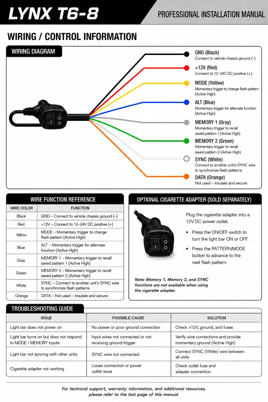
Installation Guidelines
- Select a mounting location that provides clear outward visibility and does not obstruct vehicle operation.
- Mount only to a structurally sound surface using hardware appropriate for the vehicle and application.
- Inspect both sides of the mounting surface before drilling.
- Use grommets at all wire pass-through holes.
- Protect exposed wiring with loom and secure it with cable ties.
- Confirm the light is secure and wiring is protected before placing the vehicle in service.
Operation
- Power the unit from a 12V nominal, 12–18V DC source. The optional cigarette-lighter plug includes a fuse, Dual Memory switch, and pattern button. Hardwiring requires a separately supplied 10 A fuse and fuse holder.
- On a hardwired installation, momentarily apply active-high +12V to the yellow MODE lead to cycle the 36 patterns. Left, right, and center-out are built-in selectable patterns, not separate wires or switches.
- On a hardwired installation, momentarily apply active-high +12V to the MEMORY 1 or MEMORY 2 lead to recall its saved pattern. The selected pattern saves automatically.
- The white SYNC lead connects current Lynx T6 and L6 lights. It is not available with the optional cigarette-lighter plug.
Memory Functions
The hardwire harness provides separate MEMORY 1 and MEMORY 2 leads for two saved patterns. Momentarily apply active-high +12V to the applicable lead to recall its saved pattern. The optional plug has a built-in Dual Memory switch.
MODE, MEMORY 1, and MEMORY 2 use momentary active-high +12V triggers. Do not connect these control leads directly to ground. External control leads are for hardwired installations.
Synchronization
The white SYNC lead supports synchronization with current Lynx T6 and L6 lights. Route sync wiring separately from primary power where practical and protect connections from vibration and moisture. The optional plug does not provide SYNC.
Do not connect the SYNC lead to vehicle power or ground.
Flash Pattern Information
The Lynx T6-8 has 36 selectable flash patterns. Use the MODE lead on a hardwired installation or the button on the optional plug to cycle patterns. Left, right, and center-out are built-in patterns, not separate arrow wires or switches. The selected pattern saves automatically.
Control Capabilities
- 36 selectable patterns, including built-in left, right, and center-out patterns
- Dual Memory stores two selected patterns; selection saves automatically
- Multi-unit synchronization through the SYNC lead
Final Installation Check
- Confirm the light housing is securely mounted.
- Confirm GND and +12V connections are secure, protected, and connected to a 12–18V DC source (12V nominal).
- Confirm no wiring is pinched, exposed, or routed near heat or moving components.
- Verify Mode and memory-control functions.
- If multiple compatible units are synchronized, verify all units operate together correctly.
- Confirm legal compliance before placing the vehicle in service.
Warranty & Support
Product help: customerservice@extremetacticaldynamics.com
Orders/accessories/fleet: 1-888-893-3308